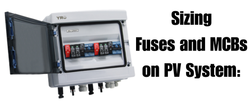
LTV Tech
LTV Tech

Blog

Safeguarding Solar Systems: PVStop and ArcBox – Your Best Defense Against PV Array Risks


At LTV Technology and Supplies, we are committed to enhancing safety and efficiency in the world of solar energy. Photovoltaic (PV) systems have emerged as a sustainable solution for harnessing solar power, but they come with their own set of challenges. In this article, we shed light on two crucial products, PVStop and ArcBox, which play a pivotal role in mitigating risks associated with PV arrays.

Understanding the Challenge

PV arrays generate clean energy from the sun, but they also carry inherent risks. One of the primary challenges arises from the nature of solar panels themselves. In a matter of seconds, the voltage in a PV array can drop, and the current can decrease to nearly zero, especially during quick applications over the middle of the panels. While regulations and maintenance efforts address some of these risks, human factors, corrosion, and neglect can still pose threats to the safety of these systems.

Regulators and authorities have been diligently working to improve the safety of PV systems, but immediate action is also essential. In this context, products like PVStop offer a powerful solution to combat these risks effectively.

PVStop: Rapid and Reliable

PVStop is the fastest and most effective way to disconnect the power source in a PV array system. Given that the sun is the source of power, no electrical device can fully replicate this function. PVStop is available in 9kg and 4.5kg fire extinguisher bottles and acts as a water-based isolating coating compound.

The beauty of PVStop lies in its simplicity. You don’t need a technical background to apply it. After a quick application, the voltage dramatically drops to a safe level, and more importantly, the current is reduced to almost zero amps. No power means no threat. Following the initial application, panels can be sprayed to cover the entire surface, bringing both voltage and current down to zero. This protective coating can last for up to a year if needed, and when the system is safe again, it can be easily removed and disposed of safely.

ArcBox: Tackling Connector Challenges

Another significant risk factor in PV systems is the quality and maintenance of connectors, particularly MC4 connectors. Research and data have shown that many PV system fires originate from issues related to these connectors. The problem isn’t solely the connectors themselves but also human errors during installation and the prevalence of subpar connectors in the market.

ArcBox, developed by Viridian, plays a crucial role in addressing these concerns. During commissioning, issues related to connectors might not be readily apparent, but they can become risks after a few years due to corrosion and poor maintenance practices.

MC4 connectors are designed with rubber seals to prevent moisture ingress. However, during installations or subsequent maintenance, these connectors are often taken apart and reconnected, compromising the integrity of the seal. Over time, this can lead to corrosion and arcing, which can ultimately result in fires.

High-quality MC4 connectors undergo rigorous testing, including water and high-temperature flame retardant tests to ensure they are suitable for outdoor use. However, even these connectors can deteriorate over time, depending on environmental factors.

In regions with high UV exposure like South Africa, maintaining and replacing connectors and safety equipment is essential due to the harsh conditions. The intense UV radiation can accelerate wear and tear on PV components.

Conclusion

PV arrays offer a promising avenue for clean energy generation, but they also present safety challenges that cannot be ignored. Products like PVStop and ArcBox provide practical solutions to minimize risks associated with these systems.

By swiftly disconnecting power sources and addressing connector-related issues, we can significantly reduce the chances of PV system fires and improve the overall safety and reliability of solar energy systems. It’s imperative for regulators, insurance companies, and industry associations to promote and endorse these products to safeguard properties and lives.

At LTV Technology and Supplies, we remain committed to promoting the safe and efficient use of solar energy. Contact us today to learn more about how PVStop and ArcBox can enhance the safety of your PV array systems. Together, we can harness the power of the sun responsibly and sustainably.

Ensuring Safety in Solar PV Systems: A Simple Solution for First Responders

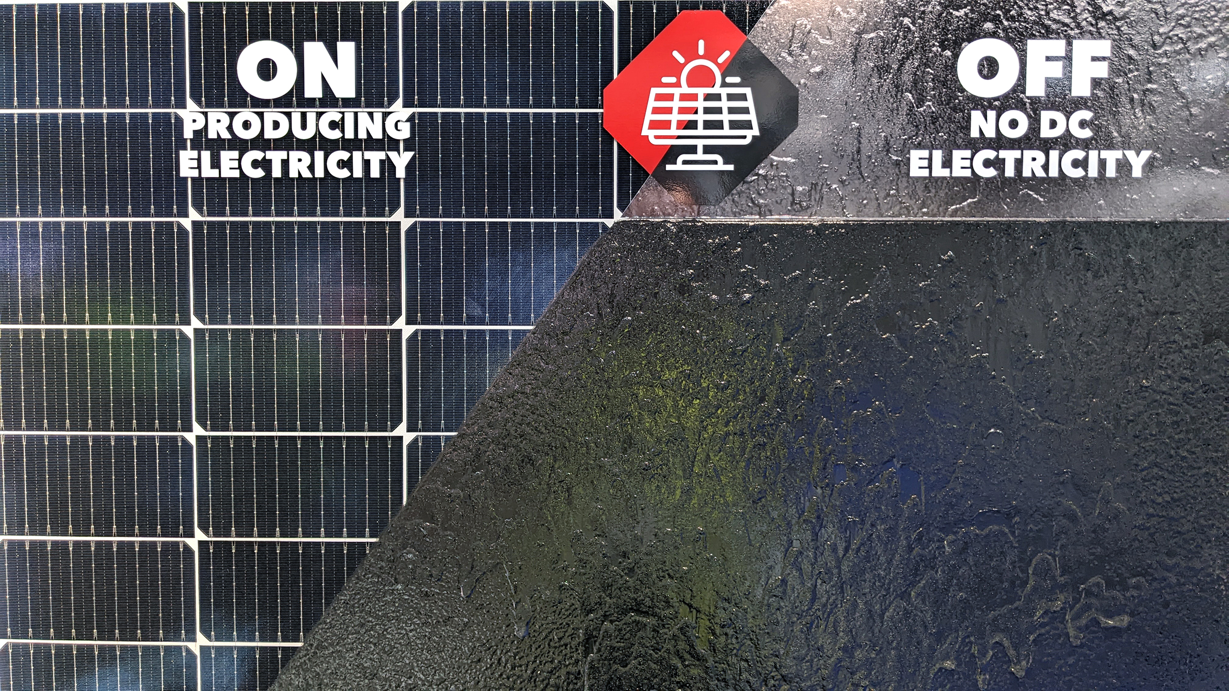
Solar photovoltaic (PV) panels are a sustainable and increasingly popular source of clean energy. However, it’s important to understand that they can also pose a potential electrical hazard, especially in emergency situations. In this article, we’ll explore the need for safety measures when dealing with solar PV systems and introduce a straightforward solution that makes these systems safe for first responders.

The DC Danger Zone:

Solar PV panels generate direct current (DC) electricity when exposed to sunlight. This DC electricity can be potentially lethal. All solar PV systems have safety features like isolation switches and arc fault detection equipment, but these operate downstream of the panels. This means that the panels and their wiring remain live when exposed to light, creating what experts call the “DC Danger Zone.”

Safety Concerns:

Fires involving solar panels should not be tackled by untrained personnel because these panels pose an electrical hazard. Compromised solar PV systems present a live DC electrical risk that can escalate into a fire if not addressed promptly. However, reporting such incidents remains challenging due to the lack of dedicated categories in national incident reporting systems.

Impact on Fire Dynamics:

Solar PV systems integrated into structures can alter how fires spread. Factors like the gap between the panels and the roof, roof materials, and the structural load impact fire dynamics. First responders may not have the technical knowledge to deal with these complexities, making it crucial to provide them with a simple and effective solution.

The Solution:

Trained personnel can apply a light-blocking coating to solar panels using a pressure vessel or drone delivery method. This coating effectively de-energizes the entire solar PV system, making it safe for first responder operations. The PVStop coating should possess additional safety benefits, such as being fire retardant, non-flammable, non-conductive, non-toxic, and environmentally friendly when disposed of.

Restoring Safe Operation:

Once applied, the protective coating can be peeled off by a qualified electrical technician, restoring the solar PV system to safe operation. It’s essential to follow the manufacturer’s recommended instructions during application to ensure that the panels are properly de-energized.

Global Collaboration:

This safety solution has been developed with input from global experts and collaborations with firefighting organizations. Organizations like the London Fire Brigade, Singapore Civil Defence, and New York Fire Department have embraced this solution. PVStop have also actively contributed to safety standards and regulations in the field.

Solar PV systems are a valuable source of renewable energy, but they come with unique safety challenges. Ensuring the safety of first responders is paramount when dealing with solar PV incidents. The application of a light-blocking coating is a simple yet highly effective way to de-energize solar panels and make them safe for emergency operations. By embracing this solution and collaborating on safety standards, we can ensure that solar PV systems continue to contribute to a sustainable future while minimizing risks.

Navigating Honest Partnerships and Quality in the Renewable Energy Sector

In the ever-evolving landscape of the business world, one thing remains constant: the value of honesty and integrity in relationships. When it comes to the dynamic field of renewable energy, fostering transparent and genuine partnerships becomes not just a preference, but a necessity.

Harnessing Your Expertise

Your journey in the renewable energy sector isn’t just about transactions; it’s about building bridges based on your knowledge and experience. Embrace your specialty, for it holds the key to unlocking the full potential of innovation and progress. By fostering an environment where your expertise flourishes, you contribute not only to your own growth but to the advancement of sustainable energy solutions.

Renewable Energy’s Promising Path

The winds of change have swept in, and the renewable energy sector is firmly establishing its presence for the long haul. Governments worldwide are constantly refining regulations to ensure the safety of installers and consumers alike. With each regulatory update, the sector becomes safer, more reliable, and better suited to shape a cleaner future.

The Quality Predicament

Amidst the promise, challenges emerge. The surge in demand for renewable energy solutions has attracted numerous companies seeking to capitalize on the trend. However, this rush for profit can sometimes compromise the integrity of products and services. Subpar components and shoddy workmanship can not only hamper the effectiveness of renewable energy systems but also pose safety hazards.

Shared Responsibility

As consumers, we play an integral role in shaping the industry’s landscape. The budget constraints faced by many can lead to compromise on quality. But remember, your investment in a sustainable future should extend beyond monetary concerns. Prioritizing quality over quantity can safeguard your investment and contribute to the overall safety of the sector.

A Wise Path Forward

Our advice resonates from a deep understanding of the industry. Instead of chasing an off-the-grid dream with substandard products, consider a pragmatic approach. Opt for a smaller renewable energy system that caters to your essential needs, adhering to international IEC standards and local regulations. By doing so, you’re not just embracing a sustainable future but also ensuring the safety and efficacy of your energy solution.

Exploring Alternatives

In your pursuit of energy independence, remember that options extend beyond electricity. Depending on your location, gas can be an effective alternative for water heating and cooking purposes. It’s all part of creating a holistic energy strategy that aligns with your needs and values.

In conclusion, as we traverse the exciting path of renewable energy, let’s remember that it’s not just about embracing the technology. It’s about forging honest partnerships, prioritizing quality, and making informed decisions that shape a sustainable, secure, and brighter future for all.

#RenewableEnergy #SustainabilityMatters #HonestPartnerships

IEC standards and Verified Certifications

In countries where national standards are not yet updated to the latest technologies and specifications in the solar industry, adhering to international standards like those established by the International Electrotechnical Commission (IEC) becomes crucial. The IEC sets global standards for a wide range of electrical and electronic technologies, including solar applications. These standards provide a common framework for ensuring safety, interoperability, and quality across different countries and regions.

Here are some key points about the importance of IEC standards and verified certifications like CE, TUV, ROHS, etc., in solar applications:

  1. Consistency and Interoperability: IEC standards provide a consistent set of guidelines for designing, manufacturing, and operating solar equipment. Following these standards ensures that different components from various manufacturers can work together smoothly, promoting interoperability and reducing compatibility issues.
  2. Safety: IEC standards emphasize safety considerations for solar equipment and installations. This is particularly important in the solar industry, where equipment is exposed to environmental factors like sunlight and weather. Compliance with IEC safety standards helps prevent electrical hazards and reduces the risk of accidents.
  3. Quality Assurance: Adhering to IEC standards helps maintain a high level of quality in solar products and systems. Manufacturers that follow these standards are more likely to produce reliable and durable equipment, which ultimately benefits end-users and system operators.
  4. Global Acceptance: IEC standards have international recognition and are widely accepted across countries and regions. This global acceptance facilitates trade and collaboration, as equipment that complies with IEC standards is more likely to meet regulatory requirements in different markets.
  5. Market Access: Verified certifications like CE (Conformité Européene) indicate that a product meets relevant safety, health, and environmental protection requirements within the European Economic Area. TUV (Technischer Überwachungsverein) is a trusted certification organization that tests and certifies products for safety and quality. ROHS (Restriction of Hazardous Substances) compliance ensures that products do not contain hazardous materials. Having these certifications can facilitate market access and build trust with customers.
  6. Consumer Confidence: End-users, installers, and system operators gain confidence when dealing with products that carry recognized certifications. Verified certifications provide assurance that the products have undergone testing by independent organizations and meet certain quality and safety standards.
  7. Regulatory Compliance: In regions where national standards are not updated, IEC standards and verified certifications can serve as a basis for complying with local regulations. They demonstrate a commitment to adhering to global best practices even in the absence of up-to-date local standards.
  8. Liability and Warranty: Adhering to recognized standards and obtaining verified certifications can reduce manufacturer liability and warranty claims. Compliance with these standards shows that the manufacturer has taken appropriate measures to ensure the reliability and safety of their products.

In summary, IEC standards and verified certifications play a pivotal role in ensuring the safety, quality, and compatibility of solar equipment and installations. They facilitate global trade, build consumer trust, and serve as a reliable reference point for countries where national standards might not be up to date with the latest industry developments.

Integrating South African National Standards (NRS) compliance with IEC standards and existing certified products is essential for the successful deployment of solar systems in South Africa. Here’s why the alignment between NRS standards, IEC standards, and verified certifications is important:

  1. Regulatory Compliance: NRS standards are specific to South Africa and outline the requirements and regulations for various industries, including the solar industry. Aligning with NRS standards ensures that your solar products and installations meet the country’s regulatory expectations, which can help you avoid legal issues and ensure smooth project implementation.
  2. Local Context: NRS standards are designed to address the unique environmental, climatic, and grid conditions of South Africa. Integrating these standards with IEC standards and verified certifications ensures that solar systems are optimized for local challenges, leading to better performance, reliability, and safety.
  3. Quality Assurance: NRS standards often incorporate elements of international standards, including those from the IEC. By adhering to NRS standards, you can ensure that the quality and safety of your solar products align with both global best practices (IEC) and the specific requirements of the South African market (NRS).
  4. Consumer Trust: For South African consumers and businesses, compliance with NRS standards signals a commitment to quality and safety. When products and installations meet both local and international standards, it instills confidence in consumers, leading to higher adoption rates and customer satisfaction.
  5. Compatibility: Aligning with NRS standards helps ensure that solar equipment and installations are compatible with local grids, infrastructure, and regulations. This can reduce technical complications and ensure seamless integration into the existing energy ecosystem.
  6. Project Approvals: Many regulatory bodies and authorities in South Africa require compliance with local standards like NRS for project approvals. By incorporating NRS compliance alongside international standards, you expedite the approval process and minimize potential delays.
  7. Risk Mitigation: Integrating NRS standards with IEC standards and verified certifications reduces risks associated with non-compliance. It demonstrates your commitment to meeting both global and local requirements, reducing the chances of accidents, failures, and legal complications.
  8. Market Competitiveness: NRS compliance enhances your competitive edge in the South African market. By offering products and services that are aligned with local standards, you position yourself as a provider who understands and caters to the specific needs of the region.
  9. Education and Training: NRS standards can serve as educational tools for local installers, technicians, and operators. Training individuals to work with equipment that meets NRS, IEC, and certified standards ensures that they have the skills needed to install and maintain systems effectively.

In summary, integrating South African NRS compliance with IEC standards and existing certified products ensures that solar systems meet local regulations, are tailored to local conditions, and maintain global quality and safety benchmarks. This alignment fosters regulatory compliance, consumer trust, and successful market penetration in South Africa’s solar industry.

We at LTV will do our best to stay within all these above mentioned regulations and to be able to get to a point where all our products get NRS approval to ensure we only supply the best safety and compliance. It does take a lot of time and money for each product but we will only import the best up to date standards we can get globally to become the lead supplier of quality and best technology products into the South African market.

Installing compliant products to standards in the wrong applications.

The Important aspect of the dangers associated with installing compliant products to standards in the wrong applications. This underscores the significance of not only using compliant components but also ensuring their correct installation and use according to the specified guidelines. Let’s break down the dangers and compare the two scenarios:

1. Installing SANS-Approved Polarity DC Breakers Incorrectly:

  • Dangerous Potential: While SANS-approved polarity DC breakers might be designed to be safe and compliant, installing them incorrectly can indeed pose significant risks. These breakers are designed to handle the flow of current in a specific direction (polarity). If they are installed in reverse or against the intended current flow, they might not operate as expected and could potentially lead to electrical faults, overheating, and fire risks.
  • Fire Hazard: Incorrectly installed polarity DC breakers could cause electrical arcing, overheating, or even a short circuit. This can lead to localized heating and ignition of surrounding materials, potentially causing a fire hazard.
  • Importance of Correct Installation: Proper installation and adherence to manufacturer guidelines are crucial for ensuring that even compliant components function as intended and do not create safety risks.

2. IEC Certified Non-Polarity DC Breaker:

  • Installation Flexibility: IEC-certified non-polarity DC breakers, as you mentioned, are designed to operate safely regardless of the direction of current flow. This provides installation flexibility and reduces the chances of errors due to incorrect polarity connections.
  • Reduced Installation Errors: The non-polarity feature minimizes the risk of mistakes during installation, as the breaker can be connected in either direction without affecting its functionality or safety.
  • Enhanced Safety: By reducing the potential for incorrect installation, non-polarity DC breakers can contribute to safer installations with fewer chances of faults or hazards.

In both cases, the key takeaway is that compliance with standards and certifications is just one part of ensuring safety. Correct installation, following manufacturer guidelines, and having a deep understanding of the product’s specifications are equally critical. The dangers of improper installation highlight the need for proper training, quality assurance, and attention to detail when working with electrical components, especially in applications as critical as solar systems.

To mitigate these dangers and risks:

  • Education and Training: Installers and technicians should receive proper training on product installation, specifications, and safety protocols.
  • Manufacturer Guidelines: Always adhere to manufacturer guidelines and specifications for installation, operation, and maintenance.
  • Quality Assurance: Implement quality control measures to verify correct installation and operation before finalizing any solar installation.
  • Supervision and Inspection: Have qualified individuals oversee the installation and conduct thorough inspections to identify any potential errors or hazards.
  • Continual Learning: Stay updated with industry standards, best practices, and advancements to ensure installations are safe and compliant.

By combining compliant products with correct installation practices, the industry can significantly reduce the risks associated with improperly installed components and ensure the safety and reliability of solar systems.

The differences between IEC60947-2 vs IEC60898-1 for DC and PV application

As of my last update in September 2021, there are some key differences between IEC 60947-2 and IEC 60898-1 when applied to DC (Direct Current) circuits. Please note that standards might have been updated or revised after my last update, so it’s essential to verify the latest versions. Here are the main differences:

  1. Scope and application:
  • IEC 60947-2: This standard specifically deals with low-voltage switchgear and control gear intended for use in DC circuits up to 2,000 V. It covers a wide range of devices, including circuit-breakers, disconnectors, and switch-disconnectors.
  • IEC 60898-1: This standard focuses on low-voltage circuit-breakers for AC (Alternating Current) circuits with rated voltages up to 1,000 V and rated currents up to 125 A. It does not directly address DC applications.
  1. Voltage and current ratings:
  • IEC 60947-2: Designed for DC circuits with voltage ratings up to 2,000 V.
  • IEC 60898-1: Designed for AC circuits with voltage ratings up to 1,000 V.
  1. Breaking capacity:
  • IEC 60947-2: The standard specifies breaking capacity requirements for DC circuits, taking into account the differences in arc extinguishing mechanisms between AC and DC circuits.
  • IEC 60898-1: The breaking capacity requirements are specified for AC circuits.
  1. Arc extinguishing:
  • IEC 60947-2: Arc extinction in DC circuits is generally more challenging than in AC circuits due to the continuous nature of DC current. The standard addresses the specific requirements for proper arc extinguishing in DC applications.
  • IEC 60898-1: Primarily concerned with arc extinction in AC circuits, which have zero-crossing points that aid in arc interruption.
  1. DC-specific performance testing:
  • IEC 60947-2: The standard includes specific performance testing procedures applicable to DC circuit-breakers and other DC switchgear, ensuring their suitability and safety for DC applications.
  • IEC 60898-1: Focuses on performance testing for AC circuit-breakers.
  1. Trip characteristics:
  • IEC 60947-2: The standard defines specific trip characteristics that are relevant for DC applications, considering the behavior of DC circuits during faults.
  • IEC 60898-1: The trip characteristics are tailored for AC circuits.
  1. Polarity sensitivity:
  • IEC 60947-2: Some DC circuit-breakers may have polarity sensitivity requirements to ensure proper operation in DC they should be totally banned and make sure to buy and install only Non-Polarity DC Breakers.
  • IEC 60898-1: AC circuit-breakers typically do not have polarity sensitivity since AC current periodically reverses direction. And can not be used to disconnect an DC arc. Therefore they are extremally unsafe to use  in any DC application

It’s crucial to follow the appropriate standard based on your specific application (AC or DC) and adhere to the relevant guidelines to ensure safety and compliance. Always consult the latest version of the standards for accurate and up-to-date information.


Make sure about the certification from your supplier. There are breaker that has certification for AC and will be used for DC and would be polarity breakers and has to be connected in specific way otherwise they could be very dangerous.

The use of A 125 Amp DC Non-Polarity MCB will fit on which size inverter and battery systems?

The compatibility of a 125 Amp DC Non-Polarity MCB with inverter and battery systems depends on several factors, including the voltage and capacity of the systems.

The amperage rating of the MCB (125 Amps) refers to its maximum current-carrying capacity. In order to determine its compatibility with an inverter and battery system, you need to consider the following:

  1. Inverter Voltage: Check the voltage rating of the inverter. The MCB should be rated for the same voltage to ensure compatibility. For example, if the inverter operates at 12V DC, then the MCB should be suitable for 12V DC systems.
  2. Battery System Voltage: Consider the voltage of the battery system that the inverter is connected to. The MCB should be rated to handle the voltage of the battery system. Common battery system voltages include 12V, 24V, or 48V DC.
  3. Battery Capacity: The capacity of the battery system (measured in ampere-hours, Ah) is also important. The MCB should have an amperage rating equal to or higher than the maximum current that the battery system can deliver. For example, if you have a battery system with a maximum discharge current of 100 Amps, the 125 Amp MCB would be suitable.

It’s important to note that selecting the appropriate MCB is crucial for the safety and performance of your electrical system. If you’re unsure about the compatibility or installation, it’s recommended to consult a qualified electrician or professional who can assess your specific requirements and provide guidance.

C/Rating on batteries – a simple explanation.

The C rating of a battery refers to its discharge rate or the rate at which it can deliver its stored energy. It is typically represented as a multiple of the battery’s capacity. For example, a battery with a C rating of 1C can discharge its entire capacity in one hour, while a battery with a C rating of 2C can discharge twice its capacity in one hour.

To determine the C rating of a battery in your solar system when it is not specified on the spec sheet, you may need to gather some additional information and perform calculations. Here’s a general method you can follow:

  1. Determine the battery’s capacity: Look for the capacity rating of the battery on the spec sheet. It is usually given in ampere-hours (Ah) or milliampere-hours (mAh). For example, if the battery has a capacity of 100Ah, that means it can theoretically deliver 100 amps of current over one hour.
  2. Find the maximum continuous discharge current: Check if the spec sheet provides the maximum continuous discharge current rating. This rating indicates the highest current the battery can continuously deliver without causing damage or significant voltage drop. It is usually mentioned in amps (A) or milliamps (mA). For instance, if the battery’s maximum continuous discharge current is specified as 50A, it means it can deliver a continuous current of 50 amps.
  3. Calculate the C rating: Divide the maximum continuous discharge current by the battery’s capacity to calculate the C rating. Convert both values to the same unit if necessary. Using the previous examples, if the battery has a capacity of 100Ah (100,000mAh) and a maximum continuous discharge current of 50A (50,000mA), the C rating would be:C rating = Maximum continuous discharge current / Capacity = 50A / 100Ah = 0.5C

Therefore, in this example, the battery has a C rating of 0.5C, meaning it can discharge at a rate of 0.5 times its capacity.

Keep in mind that this method assumes the battery can sustain its maximum continuous discharge current without significant voltage drop or damage. It’s always recommended to consult the manufacturer or supplier for accurate information on the C rating if it’s not readily available.

Safety on your Solar Panels not to be taking lightly

DC arc refers to an electrical arc that occurs in a direct current (DC) circuit. It typically happens when there is a high voltage differential and a conductive path is created through the air or another medium. The intensity of the arc depends on factors such as the voltage, current, and distance between the conductive materials.

In a typical Installation of 8 x 550W solar panels connected in series. It’s important to note that solar panels produce DC electricity, typically at a voltage range of 12V, 24V, or 48V, depending on the configuration. The total power output of your 8 solar panels would be 8 x 550W = 4,400W (or 4.4kW).

If you are concerned about the potential for a DC arc occurring in this setup, it’s essential to ensure proper wiring, grounding, and protection mechanisms. Here are a few considerations:

  1. Wiring: Use appropriate-sized wires and cables to handle the current produced by the solar panels. Consult the manufacturer’s specifications or seek the assistance of a qualified electrician.
  2. Circuit Breakers: Install circuit breakers or fuses in the system to protect against overcurrent situations and potential arcs. Properly sized and rated breakers should be used according to the current capacity of the solar panels and wiring.
  3. Disconnecting Means: Include a disconnecting means, such as a switch or breaker, near the solar panel array. This allows you to isolate the panels from the rest of the system for maintenance or in case of emergencies.
  4. Grounding: Ensure that the solar panels, inverters, and other relevant components are properly grounded. This helps to minimize the risk of electrical faults and provides a path for fault currents to dissipate safely.
  5. Compliance with Codes and Standards: Follow the local electrical codes and standards applicable to your area. These guidelines provide specific requirements for the installation and safety of solar panel systems.

It is important to consult with a qualified electrician or solar installer who can assess your specific installation and provide appropriate guidance to ensure the safety and proper functioning of your solar panel system.

Connecting Inverter to the essentials at DB Box

Disclaimer : Installing your Inverter to the DB Box. Please take note that only qualified persons is allowed to work on the DB Board, this is only for illustration purposes.
Sizing your system cables, breakers and fuses to SANS 10142-1-2:201X specifications

Pure Sinewave vs Modified Sinewave Inverters

Pure sine wave inverters and modified sine wave inverters are both types of inverters that convert direct current (DC) electricity to alternating current (AC) electricity, but they do so in slightly different ways.

Pure sine wave inverters produce a waveform that is a perfect sine wave, which is similar to the waveform of the electricity that is supplied by utility companies. This type of waveform is considered to be the “cleanest” form of AC power and is suitable for powering sensitive electronic equipment such as computers and televisions. Pure sine wave inverters are generally more expensive than modified sine wave inverters.

Modified sine wave inverters, on the other hand, produce a waveform that is a square wave or a modified sine wave. This type of waveform is not as clean as a pure sine wave, and can cause some electronic equipment to operate less efficiently or even damage them. Modified sine wave inverters are less expensive than pure sine wave inverters and they are suitable for powering devices such as lights, power tools, and motors.

In summary, if you need to power sensitive electronic equipment, a pure sine wave inverter is the best choice. If you’re looking to power less sensitive equipment such as lights and motors, a modified sine wave inverter is suitable and more cost effective.